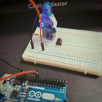
DTMerでコーヒー屋さんでも、電子工作をすることがあります。
シンセサイザー作ったり、スピーカー作ったり、アナログミキサーを作ろうとしたりと、ちょっと電子工作を齧っていた時に、部品屋さんで見かけるアイテムに「Arduino」というものがありました。
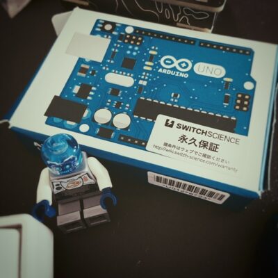
他の電子部品とは一線を画すちょっとこじゃれたデザインの箱に入っていて、そこはかとなく物欲を刺激されていました。
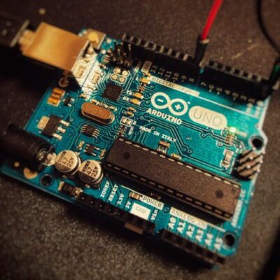
その「Arduino」をゲットして、早速ちょっといじってみましたので、その備忘録。

結論から言うと「難し楽しい!」
LEDを光らせる
参考図書として「Arduinoをはじめよう」という本をまず読んでみる。
(分かりやすくて大変読みやすいです。気さくな表現も楽しげ)
どうやらまずは「LEDを光らせる」というのが通過儀礼のようです。
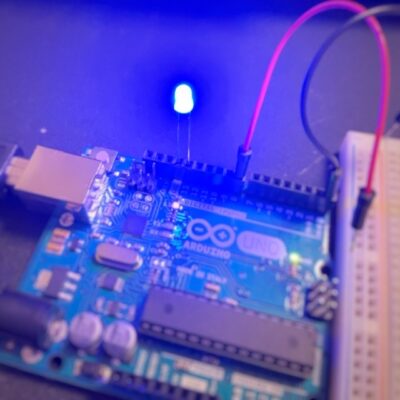
LEDのアノード・カソードを確認して端子に差し込んだところ、なぜか点灯。
中古で買ったので、前のオーナーがすでにプログラムしていたようです。
LEDって抵抗挟まないと壊れるって聞いていたけど、これは大丈夫のよう?
LEDを点滅させる
お次は点灯しっぱなしのLEDを点滅させます。
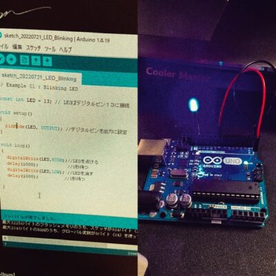
DTMerにはおなじみの「delay」をつかって点灯時間をコントロールします。
1秒の1000分の1秒から設定できるようですので、1000とすると1秒間点けたり消したり。
この辺もまだ混乱せずできております(;’∀’)
スイッチを使って点灯させる
点きっぱなし、点滅しっぱなしというのも実用性に欠けるというので、次は「スイッチを使って」点けたり消したりできるようにします。
これはスケッチ(Arduinoではコードをスケッチと呼ぶようです)が残っていたので、参考までに。
|
1 2 3 4 5 6 7 8 9 10 11 12 13 14 15 16 17 18 19 20 21 22 23 24 |
// Example 02 : ボタンが押されている間、LEDを点ける const int LED = 13; // LEDはデジタルピン13に接続 const int BUTTON = 7; //プッシュボタンが接続されているピン int val = 0; //入力ピンの状態がこの変数(val)に記憶される void setup() { pinMode(LED, OUTPUT); //ArudinoにはLEDが出力であると伝える pinMode(BUTTON,INPUT); //BUTTONは入力に設定 } void loop() { val = digitalRead(BUTTON); // 入力を読み取りvlaに格納 //入力はHIGH(ボタンが押されている状態)か? if (val == HIGH) { digitalWrite(LED,HIGH);//LEDをオン }else{ digitalWrite(LED,LOW); //LEDをオフ } } |
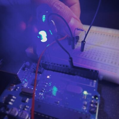
ブレッドボードに配したスイッチを押すと点灯。話すと消えます。
ショート動画にしたので、参考までにどうぞ。
https://youtube.com/shorts/MHj7towjGaA?feature=share
(LEGOがLEDを握っているのは特に意味ありません)
サンプルスケッチを試す
インストールしたArduinoのフォルダ内に「examples」という気になるフォルダがあったので、
C:\xxxxxxxx\Arduino\examples\01.Basics\Fade
「おや、この中になにかスケッチが入っているんじゃ…」
と思ってみてみると、やっぱりありました。
それをArduinoに書き込んで、同じフォルダ内にあったブレッドボードへの配線も真似してみたところ…
無事完成!
FADE
|
1 2 3 4 5 6 7 8 9 10 11 12 13 14 15 16 17 18 19 20 21 22 23 24 25 26 27 28 29 30 31 32 33 34 35 36 37 38 39 40 |
/* Fade This example shows how to fade an LED on pin 9 using the analogWrite() function. The analogWrite() function uses PWM, so if you want to change the pin you're using, be sure to use another PWM capable pin. On most Arduino, the PWM pins are identified with a "~" sign, like ~3, ~5, ~6, ~9, ~10 and ~11. This example code is in the public domain. https://www.arduino.cc/en/Tutorial/BuiltInExamples/Fade */ int led = 9; // the PWM pin the LED is attached to int brightness = 0; // how bright the LED is int fadeAmount = 5; // how many points to fade the LED by // the setup routine runs once when you press reset: void setup() { // declare pin 9 to be an output: pinMode(led, OUTPUT); } // the loop routine runs over and over again forever: void loop() { // set the brightness of pin 9: analogWrite(led, brightness); // change the brightness for next time through the loop: brightness = brightness + fadeAmount; // reverse the direction of the fading at the ends of the fade: if (brightness <= 0 || brightness >= 255) { fadeAmount = -fadeAmount; } // wait for 30 milliseconds to see the dimming effect delay(30); } |
This example code is in the public domain.とスケッチ内に記載があったので記載させていただきました。
「Fade」という名前の通り、LEDが優しく明滅して、なんかこれだけで嬉しくなります。
PWMという言葉が出てきていますが、これは「Pulse Width Modulation」の略のようで、
コード内でも触れている「~」がついている本体のデジタル出力部の3,5,6,9,10,11がPWMの出力として使えるようです。
これ応用して、Kastleの音を時間でコントロールとかできるんじゃないか…
Calibration
|
1 2 3 4 5 6 7 8 9 10 11 12 13 14 15 16 17 18 19 20 21 22 23 24 25 26 27 28 29 30 31 32 33 34 35 36 37 38 39 40 41 42 43 44 45 46 47 48 49 50 51 52 53 54 55 56 57 58 59 60 61 62 63 64 65 66 67 68 69 70 71 72 73 74 75 |
/* Calibration Demonstrates one technique for calibrating sensor input. The sensor readings during the first five seconds of the sketch execution define the minimum and maximum of expected values attached to the sensor pin. The sensor minimum and maximum initial values may seem backwards. Initially, you set the minimum high and listen for anything lower, saving it as the new minimum. Likewise, you set the maximum low and listen for anything higher as the new maximum. The circuit: - analog sensor (potentiometer will do) attached to analog input 0 - LED attached from digital pin 9 to ground through 220 ohm resistor created 29 Oct 2008 by David A Mellis modified 30 Aug 2011 by Tom Igoe modified 07 Apr 2017 by Zachary J. Fields This example code is in the public domain. https://www.arduino.cc/en/Tutorial/BuiltInExamples/Calibration */ // These constants won't change: const int sensorPin = A0; // pin that the sensor is attached to const int ledPin = 9; // pin that the LED is attached to // variables: int sensorValue = 0; // the sensor value int sensorMin = 1023; // minimum sensor value int sensorMax = 0; // maximum sensor value void setup() { // turn on LED to signal the start of the calibration period: pinMode(13, OUTPUT); digitalWrite(13, HIGH); // calibrate during the first five seconds while (millis() < 5000) { sensorValue = analogRead(sensorPin); // record the maximum sensor value if (sensorValue > sensorMax) { sensorMax = sensorValue; } // record the minimum sensor value if (sensorValue < sensorMin) { sensorMin = sensorValue; } } // signal the end of the calibration period digitalWrite(13, LOW); } void loop() { // read the sensor: sensorValue = analogRead(sensorPin); // in case the sensor value is outside the range seen during calibration sensorValue = constrain(sensorValue, sensorMin, sensorMax); // apply the calibration to the sensor reading sensorValue = map(sensorValue, sensorMin, sensorMax, 0, 255); // fade the LED using the calibrated value: analogWrite(ledPin, sensorValue); } |
光センサーを使って、LEDの光り方を調整するスケッチ。
1回目は反応が鈍かったけど、本体の「RESET」ボタンを押すと敏感に反応するようになりました。
ちょっと影がかかるだけで、LEDの光量が頼りなくなります。
これもアンビエント好きとしてはたまらん…
動画
ささっとスマホで撮影して、ショート動画にしてみました。
ブライアン御大の音色と相まってなんか物悲し気…
https://youtube.com/shorts/hRSNRXwehBc?feature=share
BastlのKastleとも繋いでみました。もうね…楽しすぎるわい…
https://youtube.com/shorts/XKjG4ALU-HE

